Full Adder Internal Circuit Diagram
A full adder circuit diagram Fast adder circuit diagram 4 bit adder circuit diagram
Fast Adder Circuit Diagram
Full adder circuit and its construction Full adder internal circuit diagram 4 bit full adder diagram
Adder full circuit two logic half gate delay combinational add numbers gates binary code diagram using find adders table circuits
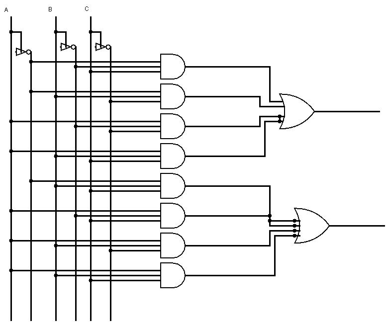
Full adder circuit: theory, truth table & constructionFull adder truth table and circuit diagram Adder logic binary circuit gates diagram using array make inputs labeled twice below also usedA binary adder made using and-or array logic.
Full adder equationAdder logic block boolean implementation Half adder circuit block diagramAdder half xor rangkaian logic ripple adders transistor kombinasi.
Full adder circuit diagram pdf
Half adder circuit: theory, truth table & constructionFull adder circuit diagram Draw the circuit diagram of half adderAdder working.
Adder binary vidi theory gupta souravAdder full diagram circuit cin theorycircuit Full-adder circuit, the schematic diagram and how it works – deeptronicFull adder equation.

Full adder circuit diagram
Full adder circuit diagramVhdl code for full adder with test bench Adder full circuit diagram using truth table carry 4bit construction schematic shown chip ttl ahead feature below lookAdder circuit diagram schematic bit full works figure.
Adder hdl and2Half adder circuit diagram using ic Full adder circuit diagram3 bit full adder circuit diagram.

Hdl – full adder schematic – frank decaire
Explain full adder with circuit diagramAdder circuit truth logic gates binary circuits introduction equations Full adder circuit diagramBinary full adder circuit diagram.
.


VHDL code for Full Adder With Test bench

Full Adder Circuit: Theory, Truth Table & Construction

Full Adder Internal Circuit Diagram

Full-Adder Circuit, The Schematic Diagram and How It Works – Deeptronic

4 Bit Full Adder Diagram

A binary adder made using AND-OR array logic

Full Adder Circuit and its Construction

Full Adder Circuit Diagram